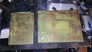
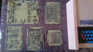
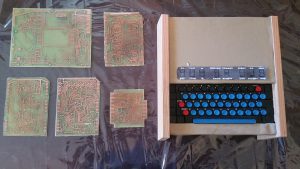
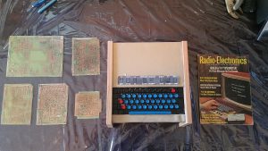
With my first test board behind me, and applying everything I learned previously, I embarked on creating the first full set of boards I needed to start building my TV Typewriter. That very first board was encouraging, however it ended up having many damaged traces because I didn’t have the vinegar/peroxide/salt etching method dialed in and left it long enough for the etchant to start getting under the toner.
After a few evenings of toner transfers and etching, at last I had a set of etched boards! Now I just had to cut them to the correct size. To be frank, I hadn’t thought much about cutting, figuring of all the technical hurdles, that one ought to be easy. Seasoned PCB makers will tell you to use something like a hacksaw. I tried that but found this FR4 stuff to be super difficult to cut through and keep from flexing while making cuts. My next attempt was with a jigsaw and special fibreglass blades. That cut the stuff like butter, but unfortunately jigsaws scratch the heck out of the boards and they’re very difficult to keep on a straight, accurate line. In fact, my first TVT ‘mainframe’ board suffered an accidental detour into one of the traces. Ugh! Luckily I had more than enough board available to make another one, and I had thought about it anyway as I was still getting the etching process down pat when it was done and again, there had been some intrusion of the etchant onto the protected copper.
On the smaller boards, I went with tin snips. Those were quite effective and accurate, but they had two problems: one, they tended to break the board apart internally, leaving little whitish splotches along the edge. Also, these boards were fairly large, and the snips would only cut an inch or so before it became impossible to operate them. Plus, the force required to cut would give a healthy 20 year old instant arthritis!
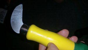
In the end, a trip to our local Rona store proved to be most helpful. The gentleman there introduced me to a ‘laminate scoring tool’:
This little guy has a hard carbide tip. You use a ruler as a guide and then press and drag the tool tip along it, scoring a groove into the board. After a couple of those you can forgo the ruler and just keep carefully pulling the tool across. Eventually it digs out enough of a ‘trench’ that you just bend and snap the excess material off. Woohoo! Nice, clean, almost professional looking boards!
Obviously we have to do a lot of drilling, and for that I got myself a dremel press, which I hooked up my Dremel 4000 to. That’ll be another story for another time but essentially I’m seeing how difficult it is to keep the bit on target (and not break it in the process).
With the boards all cut out, I decided I did want the parts placement ‘silkscreen’ on the back. Although I’m pretty sure the prototype didn’t have this, from a practical perspective, given my limited experience with homebrew electronics, I figured this would be really useful. As mentioned previously, the instruction documents included these, which apart from some ‘shadow’ traces to show the builder where traces on the other side were located, were identical to the silkscreen treatment SWTPC did on their own boards.
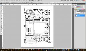
I decided I’d make use of Photoshop and the Threshold tool again to make those shadow traces disappear. Here’s before using the Threshold tool (note the light gray representations of the traces on the other side):
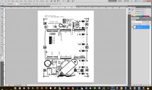
And after:
The Threshold tool can be a bit tricky here — some of the ‘shadow’ traces are really difficult to eliminate without affecting the ‘silkscreen’ stuff I want. Some of the resulting silkscreen stuff will be a little bit less than ideal quality wise.
Then I just had to mirror the image, print it on my Hotrod paper, and after careful alignment to the front side of the board, iron it on. Turns out ironing toner directly to the fibreglass of the PCB is even easier than to copper.
After repeating this process for all of the boards, at last, I have a complete set of TVT boards ready to begin building!
I should mention that fifth, smallish board on the bottom right — that is Don Lancaster’s original ASCII encoder. I believe this is the one that was used in his prototype. Shortly after the article on the TVT was published, Don designed a second, simpler one. I chose the older design just to be on the safe side. It’s quite possible he might have used a prototype of the new design in the prototype TVT, but I’m thinking it unlikely. Interestingly, the old encoder is exactly the same depth as my MDS/Microswitch keyboard.
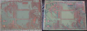
Oh, and remember I said photos distort things like colour? Check this out. I’ve put a photo of my new ‘mainframe’ board side by side with a photo of the old. The original is to the left, my new is to the right.
A good reminder, again, that photos can kind of trick you. My boards don’t look quite that green in person, but then, maybe the originals don’t either?
By the way, for my ‘silkscreen’ layer, I don’t actually have to leave it black — apparently I can get something called ‘white toner reactive foil’. Basically you iron/laminate it to your ‘silkscreen’ toner, and it leaves a white residue, instantly converting the silkscreen from black to white! I’ll have to get some of that and try it out. The black looks nice and crisp, but white would just bring it that much closer to ‘originalish’ look.
Anyway, now the hard part begins. I need to secure the remainder of the parts I need (resistors, caps, molex connectors, etc). And I need to get drilling, which I know now is going to be pretty tricky. Never mind turning it all on and trying to get it working! But at least now I have the main bits — and this whole process has inspired me to keep at it.

