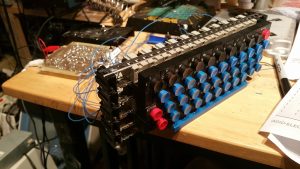
Okay, this is where the rubber hits the road, sort of. With the encoder tested out working, now we begin the laborious process of rewiring this Mohawk Data Sciences (actually Microswitch) key-to-tape keyboard. This is essentially the exact same keyboard Don Lancaster used in his prototype. It’s not clear if he used the earliest version of his ASCII encoder with it, although to me that would make sense. Interestingly, the encoder’s mounting points seem to match the keyboard’s depth.
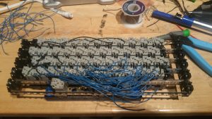
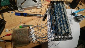
Anyway, here’s the hot mess we are presented with, as it was cut from its machine:
Actually in this pic I’ve already started removing wires. I need to remove all of them, because the encoding scheme used here was probably EBCDIC or baudot or who knows.. whatever Mohawk used. We need ASCII.
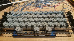
Once fully desoldered, I figured I’d start working my way from the top of the keyboard down. This is where care and attention must be paid, join the wrong wire, and you’ll get the wrong result. Early on I decided on a scheme whereby, looking at the back, I would use the left post for each key to connect to the pin marked specifically for that key, and the right post would connect to the pin corresponding to the last three digits. So for example, keys 0-7 would all be chained together on the left:
And so on for each group of keys corresponding to the appropriately marked pin on the encoder. Then on the last key in that group, a wire would connect to the encoder’s pin.
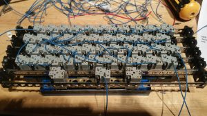
Now where it all gets tricky is when we start connecting the pins corresponding to the last three bits. To give an example, keys “, 2, B, R, :, J and Z all use 010. So these are the keys that have to be connected together on their right post, and then that line would go to the pin marked 010 on the encoder. Get it? You really gotta keep your wits about you. If I’d been smart, I would have first marked all the keys on their backsides so I didn’t have to constantly flip the keyboard over and check which key I was connecting to. Further, as you connect more keys, the wiring gets progressively messier and more dense, which makes it harder to tell where you’re going. An even smarter strategy might have been to use color coded wires to make seeing the links easier – but I was determined to use the keyboard’s original wires to keep as close to prototypical era as I could.
In the above pictures you can see this taking shape. To make things a tad easier, I did resort to using a Dymo labeller to label the wires that end up connecting to the encoder.
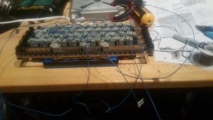
Finally when this was all done, I connected each wire to the appropriate pin on the encoder. I declined to use a connector for this, which would have allowed easy removal. I just didn’t have one and didn’t want to wait. I figured this would be stronger anyway. Here’s the final result:
I can clean this up a bit for the install, but yeah. What a spaghetti mess-o-wires!
I regret I don’t have a video to show the testing. I don’t have a tripod for my camera. Essentially on testing we had some fairly positive results, however as expected some keys turned out to be wrong. What I had expected to happen had in fact happened: I had gotten some keys mixed up. In some cases I goofed and put a wire that should have been on the left post to the right instead. In others I simply mixed up which key belonged on the 3 digit binary line, which confused the encoder. Naturally I didn’t catch this of course until I had desoldered and resoldered the keyboard connections to the encoder three times, convinced I had an undiagnosed encoder problem. But eventually I figured them out, traced the wires and connected them to the right places, removed some solder bridges, and now it works perfectly! Wow! So chalk up a successful project there! This gives me hope we’ll have good sailing during the actual TVT build.

