As I mentioned earlier, I had been procrastinating on starting my TVT build for months. I had it in my head that I could not begin until I had everything, and could build the boards sequentially starting from mainboard up to all the others. One reason for this was I wasn’t really sure how some components would fit. Thus, I might want to drill holes larger than I had in the PCBs. This is trickier to do when the boards have parts installed.
In the end though, I realized it could be a while before I found the remaining parts I needed, and if I didn’t get going soon with each passing day I might not ever.
So I decided not to go sequentially, and picked a board to start with. The Timing board seemed like a nice one – fairly straightforward. I had all the parts necessary except the crystal, which I’m working on.
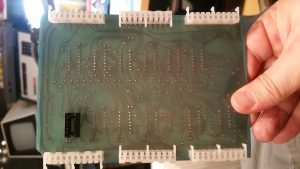
The first bit of business was getting the molex connectors for the device’s bus in place. Initially I couldn’t quite visualize how all this went together. There is a female molex connector that sits on the top, non-copper side of the PCB. Like so:
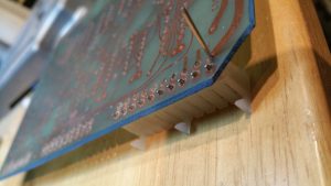
It is soldered in on the bottom. The connectors are arranged in such a way that pins installed and soldered beside their own pins underneath line up and press into the connector beneath.
My concern primarily was how to ensure the pins were strong enough to sustain the force necessary to slide in. Throughout the course of the build and testing, and later on as the unit aged, I’d probably need to repeatedly assemble and disassemble.
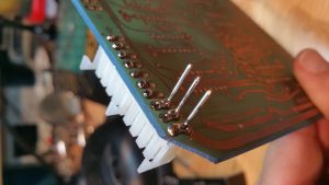
Initially I thought about molex headers. I’d mount them such that the plastic casing around them was on the same side as the female molex connectors. But this wouldn’t work — the molex connector overhangs the hole where the bottom pins come up. Nothing could fit under there. I ended up buying headers with the pins spaced incorrectly on purpose, just so I could pull the pins out one by one and solder them like so to the PCB:
Once you see it in person, it starts making sense. The long individual pins basically slide through their hole and butt up under the lip of the molex connector up top. It doesn’t matter if they make contact with the molex connector’s own pins – they’re all on the same trace anyway. Then it’s just a matter of getting the pins aligned properly and soldered in.
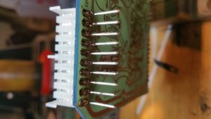
I should mention that one other worry I had about this setup was that these pins would be vulnerable to breakage. There’s really not much holding them to the board.. just the thin slice of copper trace they’re soldered to. But a quick test proved they were more than strong enough to hang on through several plugging/unpluggings. I did have to repeatedly adjust to get them nice and straight and spaced evenly, but eventually I got the first row done:
Yay! Now just.. oh.. several dozen more to go!


