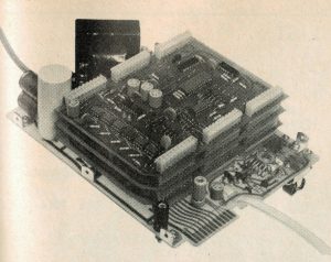
Just for clarity, what Radio Electronics refers to as ‘the Mainframe’ is what you and I today would call the ‘motherboard’. Just to clear that up in case it causes confusion among those who think of mainframes as something else entirely.
I ended up making three motherboards. The first was my first-ever homemade PCB; and it showed. I rejected it outright for overetching and bad cutting. The second was much better, but had a few spots of copper remaining where I didn’t want it. I decided to use that one to try doing ‘silkscreening’ on the backside using laser toner. The third board is the one I’m starting with. It benefitted greatly from my newly acquired knowledge about etching, cutting and so on, and looks really clean. Let’s get started.
I should note I decided late in the game to forgo silkscreening altogether on my prototype. I don’t know why I was so fixated on it. As we can deduce from this photograph, the prototype does not have it:
So that lets me off the hook. And anyway, the original silkscreening on the SWTPC kit boards was white, and since I don’t have a (expensive) printer that can print with white toner and I’m not willing to shell out to make an actual silkscreen, I’m going to leave the silkscreen off.
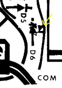
Again before embarking, I decided to check the appendix at the end of the construction guide for any last minute warnings about the mainframe. Sure enough, there was one. Diode D6 is shown backwards on the parts overlay! Luckily, the overlay I borrowed from SWTPC.com had it corrected already:
I’m glad they caught that 40 years ago and that I didn’t have to spend a week or two puzzling over schematics.
Oh and did I mention the schematics themselves have errors? Yikes! Several corrections are made in the construction guide appendix.
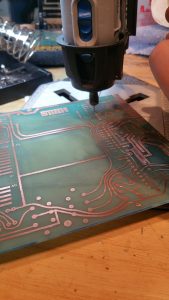
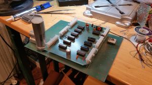
Per the guide, I want to get molex connectors installed first and check fitment. It takes minimal time to drill these out on the PCB and then solder them in:
The Dremel does a decent job, although it does have a tendency to wander. Once you get used to this though it’s easy enough to adjust your entry point to get your holes where you want them.
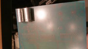
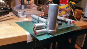
In the event, I decided to drill out the entire board, carefully looking at the photos from that ebay auction I missed to make sure I drilled the right size holes (more or less). I then couldn’t resist installing some of the capacitors:
Originally I was going to use these vintage looking blue Rubycons for the twin 1000uf caps, but along the way to getting here I found these mint condition Temple units. They look much closer to the prototype’s design and are shorter than the Rubycons, so they fit better on the board. In the end I decided to stack them just as Don did on the prototype. There’s a practical reason for this – the 5000uf cap is huge and cuts uncomfortably into the space you need for the first 1000uf cap. Stacking them frees up room.
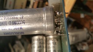
I also switched from a modern 4700uf cap to a Mallory 5000uf unit. These tall metal caps are way more authentic looking to the early 70s than the modern ‘sausage’ ones. Unfortunately these caps are the ‘slot terminal’ type. They have three contacts around the outside (for negative) and a fourth on the inside (for positive). I had to jury rig it with 14 gauge wire to make it work with my board.
This prompted some tut-tutting online, as it’s not the way these bladed units are intended to be installed. The soldered on wire terminals are weaker than the mounting plate it’s meant to use. However, I did wiggle it a bit and found it to be fairly solid. This could all be moot anyway – caps do not store for long periods well and even though these are all NOS, there’s a good chance they may be all dried up and will have to be replaced with modern. Fingers crossed!
After the molex connectors were installed, I decided to try installing the Timing board to see how it fit:
Okay so it looks good, but unfortunately it turns out I was indeed a victim of scan skewing. One of the molex connectors is skewed just slightly off to the right, so it is not straight in line with the others and requires an uncomfortable twisting of the back end of the Timing board to get it to mate. I ended up removing the Timing board and adjusting the pins as I had them pointing outward somewhat rather than straight down. This helped, and the Timing board now snaps much better into place!
That’s all we’re doing today! Looking good so far!

