Probably the most important circuit on this whole device is its RF modulator. The RF modulator takes is essentially a ‘converter’ that takes a pure video signal and emits it at a frequency a television receiver can pick up. As has been explained to me by folks more knowledgeable than I, the RF modulator is essentially a Hartley LC circuit.
In the TV Typewriter, a coil of solid wire is fed current to produce oscillations at a frequency your television set can intercept and interpret. There is a 33pf trimmer capacitor installed alongside that allows you to precisely trim the signal. For example, if I wanted the system to use channel 2, I’d need to adjust until I was putting out signal at 55.25mhz.
Setting out on the project, I had been advised by both contemporary and historical sources not to bother with the modulator and instead just pipe video direct to composite monitor to make it easy on myself.
However to me, the whole point of a ‘TV Typewriter’ is its interface with a TV. Sure, you could have bought a monitor back in the day, but monitors were expensive. The genius behind the TV Typewriter was the realization that most people already had a perfectly good ‘monitor’ in their home – their TV! To build the TVT without a TV interface just seemed pointless. After all, I already have a TVT-2 that does direct composite output.
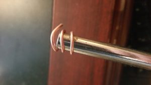
Probably I will come to regret this decision later. I did run into some snags trying to make my coil. The article advised I needed to take a 4″ piece of solid 14 gauge wire, and twist it 6 turns on a 3/8″ mandrill, spacing the turns so that the whole coil is about 1″ long. Well, here’s how many twists I was able to get with 4″:
Hmm. I decided to write Don directly about this. This wouldn’t be the first error encountered in the directions. I asked him if I could go longer and what the implications would be. He said no problem (‘shouldn’t be critical’ were his words) and gave me some pointers on what I was shooting for frequency wise.
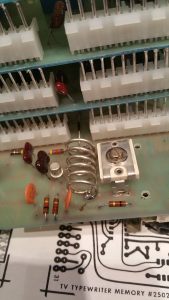
I ended up taking a 7″ long piece of wire and got my 6 turns out of that. With that all shaped up properly, I then turned my attention to how to fix it to the mainframe. Obviously I can’t direct solder the ends as they have to pass through to the copper traces on the opposite side of where the coil is mounted. I couldn’t see clearly enough in any pictures of originals I had if they had used special mounts, so for the ends I just soldered in two solid wire ‘posts’ and then soldered the coil ends to that.
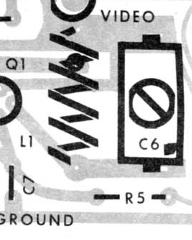
That seemed straightforward enough, but I was at a loss as to what to do about a third connection implied by the drill pattern on the PCB:
The instructions, being written for people who actually knew what they were doing, did not explain. Was that another mount point? If so, why?
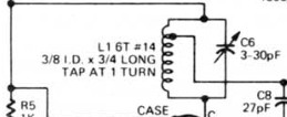
This is where it helps to read schematics. The schematic is specific that you must ‘tap’ (attach) a third point to the coil on the first turn:
Why? Not being an electronics expert (yet), I can only hazard a guess that current is passed from one end of the coil to the other, and the third ‘tap’ is placed at a point where sufficient signal/oscillation is generated to be usable.
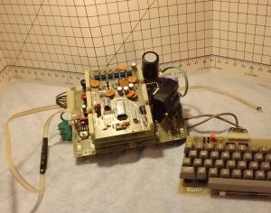
The trace the third tap is on leads directly to the 300ohm twinlead, which is a flat ribbon-like cable those of us over a certain age might call ‘antenna cable’. You can see it on Roy’s unit here – it’s long and flat and has two little ‘Y’ connectors that screw into the TV’s VHF antenna terminals at the back:
This is more or less the TVT’s antenna, carrying signal from the unit to the TV to intercept at your chosen channel. As I said before, a lot of TVT builders ran aground on this particular rock. Bob Rethemeyer ran into this particular problem when he built his – the output was apparently terrible. Apparently it requires a lot of fidgeting to get working properly, and that’s why so many chose to just direct the feed to composite monitors or gave up entirely.
Anyway, here’s the circuit more or less completely installed:
Personally I think RF output will be the least of my problems getting this thing to actually run. But, we shall see!

