Okay so let’s start with what I had to do to make some period correct looking Mark-8 PCBs.
One thing I’ve had to learn the hard way with the toner transfer PCB-making process, is that it really relies on good quality artwork. If you’re working third-hand with someone’s low quality scan of original artwork, you’re going to have a problem.
While initially my first attempts at making a double sided Mark-8 CPU board looked successful, when I examined the finished product more closely with the eyes of experience from my TVT project, I realized it wasn’t. Looking closely at the traces, I could see a ‘pixelated’ pattern which I think was a result of the dithering from the low resolution, greyscale scan I had been working with.
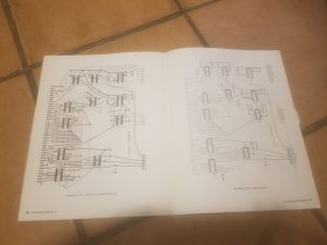
Some months after I made that first board, I came across an auction for an original TV Typewriter. I lost, but the seller, a generous fellow named Roy, offered to send me a ‘consolation prize’ in the form of an original Mark-8 construction guide! Having an original booklet in my hands meant I could experiment and try to get the best possible scan quality, with an eye towards making new boards rather than just archiving history for others to read. I would try to get the traces as dark and thick as possible, to better accomodate my “ironclad” toner transfer procress.
The first thing I did (carefully) was fool around with my guide and my day-to-day Brother all in one scanner. However, the scanner’s top end resolution is only about 600dpi, and I was finding it was distorting the artwork dimensionally.
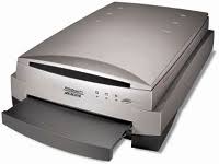
I then remembered that I had a much, much better scanner tucked away in a closet. This was a professional photo scanner, given to me by a late client of mine. It is a Microtek i900, an older scanner but with a still-impressive 6400×3200 resolution capability. The resolution in particular is fantastic – I’ve actually been able to scan stills from 8mm film and get pictures out of them!
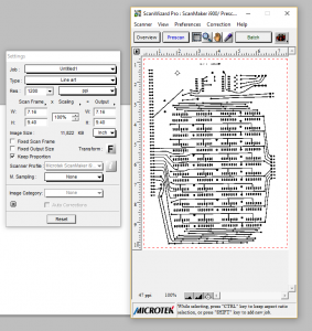
Microtek gives you a pretty nice interface software-wise. I am setting this to a strict black and white line art mode. Getting the traces perfectly black is very important. Greyscale printing at less than 100% black means you run the risk of having thin traces. I want my Laserjet 4250 to paint those traces on nice and thick. I also want to have pure black and white (line art mode, to the scanner) so that there is no in between anywhere I don’t want toner – no ‘grey’ patches that will resist my etchant, leaving me with unsightly splotches or bridged traces.
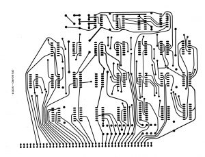
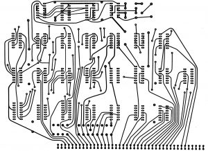
To really make sure I get it all, I set the scanner to 1200dpi. It takes a couple of minutes at that resolution to get it all in, but the result is fantastic – crisp and clear with no fuzziness:
I decided to print it off on an overhead transparency sheet to compare it to the original. To my amazement, there is no distortion whatsoever. The scanner rendered a perfect copy! Yahoo!
Now I need to clean these up and prep them for transfer to copper. One thing I will take the opportunity to do here is put some pin holes in the IC pads. This will make drilling easier. I’m doing this all one one side, and only in a few places on the other. It’d be difficult to get all the holes lined up properly so I’m sort of saving some energy here. I’ll simply drill from the side with all the hokes, and then use the few I’ve made on the other side for aligning both boards. I’ll also flip them so that they come out the right way when ironed on.
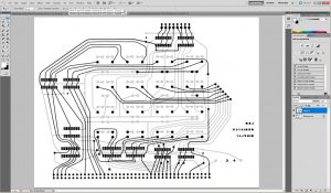
Just as I did with my first attempt, I need to use Photoshop to get the two sides nicely aligned with one another so that when they are produced as a board, there won’t be any pads or holes out of place. I made a good call in checking this, rather than trusting that if my transparencies matched the plans, all would be ok. As it turns out, the two sides for each board in the plans do not always align! I don’t know if this is printing errors, or the effects of 45 years of humidity changes, but they definitely do not. So here’s photoshop at work again. Basically what I do is temporarily convert the images to grayscale (this allows me to create layers). I then copy one side of the board I’m working on and paste it over top of the other. I then scale back the opacity on the new ‘layer’, such that I can see through it somewhat. This’ll let me get them lined up. For the actual line up process, I’m using a variety of Photoshop tools including scale and warp.
With that squared away, I move on to toner transferring and etching. First I print them off on my Laserjet 4250 on the ‘super glossy’ setting, which prints nicely on magazine paper (and slowly). As I’ve mentioned before, I use my totally unpatented 2-5-2-2 process to get a nice crisp image from my iron. It really helps that my printer lays on the traces nice and thick solid black here. What a help that is.
When I’ve got both sides for a board ready, I trim them with my scoring tool, and then dip them in my vinegar/salt/peroxide bath. I’m still feeling my way around with this process but I’m learning that it’s better not to apply the salt directly on the copper. It actually can cause pitting and even will peel the toner resist away from the board, which wrecks your traces. Another thing that can happen: put too much salt in and it will cause a very strong reaction with can discolour the PCB substrate with an ugly yellow/green. To avoid all that, I pour the salt in alongside the board and then just sort of swish the etchant tub back and forth gently. I set the whole thing in a sink of hot water to help the reaction along. Anyway, it’s a slow process but it seems to leave the PCB unscathed.
Now here’s the hard part – gluing the two sides together. I thought this would be easy – just paint some epoxy on both sides, press em together and…
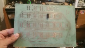
Meh. I mean, it’s functional — the epoxy works, but I’m left with these ugly splotches, like the one on the lower right in the photo. What I find out the hard way is, the epoxy is almost impossible to brush to a consistent level across both boards. This produces spots of varying sizes and darkness when you press them together, which do not look period correct or correct at all. I’m trying to make these boards look like they were original single piece double sided boards. That is not what we are getting here.
I’ve got to think about this now and try to figure out how to make this work. Some have suggested getting a book press to clamp the boards tightly and squeeze all the air out. But that’s another expense for something I won’t use that often, and book presses are pricey as well as heavy! Hmm. I think before I go that route, I’m going to have a look at other adhesives…
