Alright!
In my last post, I finally got my TV Typewriter to actually display something onscreen! It wasn’t much, but seeing 16 rows of 32 well formed boxes on my screen made me feel like I’d reached low earth orbit, and was now on my way to the moon.
According to the TVT construction guide, the next step in our journey is to add the fabled 2513 character generator. This is exciting because this is the point where the TV Typewriter actually starts putting recognizable stuff onscreen! The instructions advise strongly to check all the power pins. These ICs were rather exotic in their day (and pricey), and frying one in 1973 did not mean a quick call to Mouser.
Applying what I’ve learned so far, I check all the voltages and they’re all good. I also apply extra caution and check all around for shorts caused by bad soldering or solder flux. Where I see shiny flux where it shouldn’t be, I use a tiny jeweller’s flatblade screwdriver to scrape it out. Not the ideal way but effective.
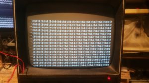
The construction guide advises the next step is to plug the board into the other two TVT boards, connect TV or Monitor, and fire it all up. If all is ok, I should have a whole screen of @ symbols (this is the default binary code the address lines produce if nothing is trying to change them). And we do!
Woohoo! Now, I do see one little problem – there are some pixels activated that shouldn’t be. I’m reassured by more experienced hands that this is likely just a short somewhere.
Still, the amazement isn’t wearing off. This is a fairly complicated electronic device and I’ve got it working! So many TVT builders before me did not even get past the planning stage, let alone get (mostly) working video output!
Ignoring the extra pixels for now, I now craft a ‘330 ohm jumper wire’ by attaching a 330 jumper to one end of a solid core #22 wire. The goal here is to attach one end of the jumper to one of the +5V ‘ports’ on the bus, and then briefly touch the other end to the ‘signal end’ of each resistor tied to the 2513’s address lines. The result should change the screen full of @s to As, Ds, Hs, Ps or blanks. At least, according to the manual. I try this out, and it sort f goes as I’m expecting, except when I connect R49, I get a B instead of P. About 30 min of fooling around ensues. I’m sending off what I’m getting to my vcfed friend Chuck, and he’s suggesting I’ve got something backwards, or that possibly the documentation is in error. Eventually we figure out that B is what should be produced, not P, and that I’m suffering from a bit of PCB dyslexia and mixing up which pins are which on the 2513. Once we account for that, we’re all good!
The next step according to the manual is to add the 2518 shift register. This another rare IC, especially one dated to 1973, and I’m a bit nervous about plugging it in. But after checking and rechecking, I go for it. Now comes the real test – jumpering in several ‘clock’ wires from marked points on the timing board to bus ‘ports’ B1-B7, to try and get the TVT to produce a full screen of all available characters. This should be interesting!

