So with trepidation I install one of my precious 2518 line register ICs. I have several of them, all dated to 1973. I got very lucky finding these with acpsurplus on ebay. I grabbed all they had, figuring there would be some attrition due to age and some mistakes on my part. I just need *one* of the eight I’ve bought to work. Can’t be that hard, right?
Anyway, I put it in there , and follow the directions in the Construction guide to connect my 330ohm ‘jumper’ to each of the bus ‘ports’ (pins) on the memory board to see if I can produce the same characters I was producing earlier by connecting the jumper to the resistors. The difference here is that where before I was simply forcing certain bits high or low on the 2513 and thus it was spitting out whatever character the resulting ASCII code produced, this time I’m actually invoking the line register and getting the TVT to ‘store’ these characters for eight lines at a time.
I confirm with my jumper wire that I am getting… nothing.
None of the bus lines I probe work. Something is wrong. I try some elementary probing around trying to understand what is (or isn’t) happening. The best I can come up with is that either my 2518 is bad, or we have perhaps a short or something not connected.
I decide to remove the Memory board and do some more cleaning between IC pins and such, to make doubly sure we have no accidental bridges. When I plug everything back in and power up again, this time I have a screen full of < symbols instead of @. If I remove the 2518 line register, it goes back to @. As I fiddle around with the board, testing continuity, making sure the sockets are ok, each time I power up things change a little. Sometimes I’ll get columns full of letters.
After scratching my head, I turned to Chuck on vcfed. Since we know the line counter is derived from the outputs of IC5 on the timing board (a Signetics 8288), we should be seeing pulses on pins 2, 9 and 12. We should also see signals on IC7, pins 3 and 8.
I decide to do a general checkover of the Timing board and discover that the socket at IC9 is bad. I was supposed to have a pulse at pin 17 but did not; with the socket replaced we’re good. But we’re still not getting any joy – pin 4 on the 2518, which should have a pulse, is solidly high according to my logic probe. Why?
It turns out that the problem is pretty elementary – bus pin 17 on the memory board was not making direct contact with the attached trace. Pin 17 is the line 1, 13, 25 transfer pin, so without a connection there we’re not going to see much. I’m flummoxed as to how this could be, since there was no obvious break – it looked like the pin was solidly in there. Anyway, I correct this and solder the crap out of it, and now we’ve got a connection, and now we’ve got some action when I connect my jumper. Sure enough, the characters displayed onscreen are changing into different letters as they should be! Wahoo!
So that’s a good result. Now comes the bear: I need to create some jumpers that connect to various clocks on the Timing board for the next test. Gingerly I take the unit apart and jumper in a few of the clocks recommended. When connected to B1, they should produce different ‘stripes’ of characters on the screen. For example, connecting clock ‘R’ to B1 should give me a screen that is half @s and half blanks. The Q clock should give me two vertical columns, or ‘stripes’ as the guide calls them, with blanks in between. That seems to be what I get, except I’m getting A’s instead of @s in some places.
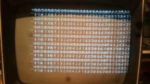
I’m not sure what the deal is there, but I decide to persist a bit further and try connecting the 0, I, H, G, F and E clocks to B6 through B1 respectively. This should produce a full screen of all the characters the 2513 can produce. I connect, power up and:
Cool! I mean, not quite what I should have, but we’re definitely getting there. Still gotta address those vertical bars in my character output, but I can see we’re a good chunk of the way there.
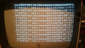
Unable to find a problem with the IC sockets or anything amiss with bridged IC pins or broken board pins, I decide to swap ICs around to see what happens. The TVT uses 4 8288s, so swapping them around in theory shouldn’t produce any change if they’re all working. However, when I swap two, I do get a slightly different pattern. I also notice that some characters in the middle of the screen are changing on the fly. After subbing in another 8288 and swapping around with no change, I decide to look at the 2518 on the memory board. On a lark, I swap it with another that i have. Sure enough, the screen changes.. but it’s worse. So I grab yet another. I’m getting ABC as I should but then it all goes bad from there.
I try subbing in another 8288 and do another 8288 shuffle, and now I’m very close:
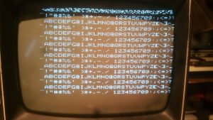
I really want that vertical line gone though. Chuck suggests checking IC10 on the memory board – a 74165. Chuck explains that since the characters are being formed on a 5×7 matrix, the 74165 is programmed to add two blank dots on one side of the character and one on the other. Since the vertical lines appear to be happening on the 4th column of dots, we trace that to output pin 2 of the 2513, which feeds into pin 14 of the 74165. He suggests something here might be amiss, maybe a short, and it’s causing the 74165 to pass on an extra vertical column of dots that shouldn’t be there. Sure enough, with a bit of hunting I realize that a jumper that connects pin 14 of the ‘165 to the 2513 output hadn’t been properly soldered! With that fixed, voila:
That’s almost perfect. Granted, we still have an @ where there should be an H. Why is that? Everything looks good. Chuck suggests that without a logic analyser or ‘scope, it’s going to be a real challenge to sort out.
I spend a full week trying to hunt it down, but to no avail. Despite checking and rechecking the boards, the ICs, the sockets, jumpers… everything… I just can’t find it. I speculate on causes and try my best to interpret what is going on. I even consult the guru himself, Don Lancaster. He gives me a few cryptic suggestions but nothing seems to change matters. I finally decide, on Don’s advice, to leave it aside for now and move onto building the Cursor board. We’ll have to hope whatever this is is just a problem with this particular test, and not a real problem with the unit.


